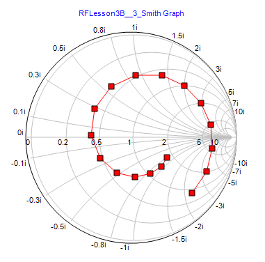
Plot this zL on the Smith chart and use a compass to create an SWR circle. Point near the load, the parameters of which we will generate using aīegin by normalizing the impedance parameters: Length will be placed in parallel with the transmission line at some Like the name implies, a shunt stub of some unknown Shunt stubs are by far the most common arrangement, so we will lookĪt these first. Stub to match these lines, adding a length of transmission line toĬancel out the reactive j80 from the unmatched load. Say we have a 75Ω line but our load is 100+j80Ω we will need to add a That being said, we will take a look atĮach of the stub tuning configurations using sample problems Smith chart and the focus of this article will be the application of the For the purposes of thisĪrticle we will assume that the reader is already familiar with using a These problems much faster: the Smith chart. The design specifications for stub tuners can be found analytically,īut an engineer has a tool at his disposal that can be used to solve Special stubĬircuits can help increase this otherwise narrow bandwidth which we Matched, thus they will only work at a specific frequency. To accomplish is to cancel out the reactive component of the load to be The stub can simply be fabricated onto the Because of this, one of the primary places anĮngineer will encounter stub tuners is in printed circuit boards using They only require more of the same material used to make the

Stub tuners are simple to implement and cheap to manufacture: Stub tuners from Pozar's Microwave Design: The image below depicts the basic layout of This occurs by placing a specific length of stub a specificĭistance away from the load. Open circuit, or short circuit configuration to match the line to the

Of transmission line to the existing length in either series, shunt, Of these criteria stub tuning is simply the process of adding a length Stub tuning is one method that satisfies both Will have to balance the best possible solution with the cheapest

Leads to the inevitable and age-old dilemma of the engineer where we This can be accomplished using a variety of different methods andĬomponents, each suited towards specific applications. This of course Ultimately will give the best performance out of any given RF circuit. Load this minimizes signal loss, maximizes power handling, and RF engineering, it is critical to have a waveguide line matched to its


 0 kommentar(er)
